14 The Stars of Other Systems
2In the design of a connector simplicity in one part may demand specialization and the establishment of hierarchies among other parts.
3 The sketches of a joint of an icosahedron show examples of different ways of joining the five edges of an icosahedron. The parts remain identical if they trade or share with each other at the joint.
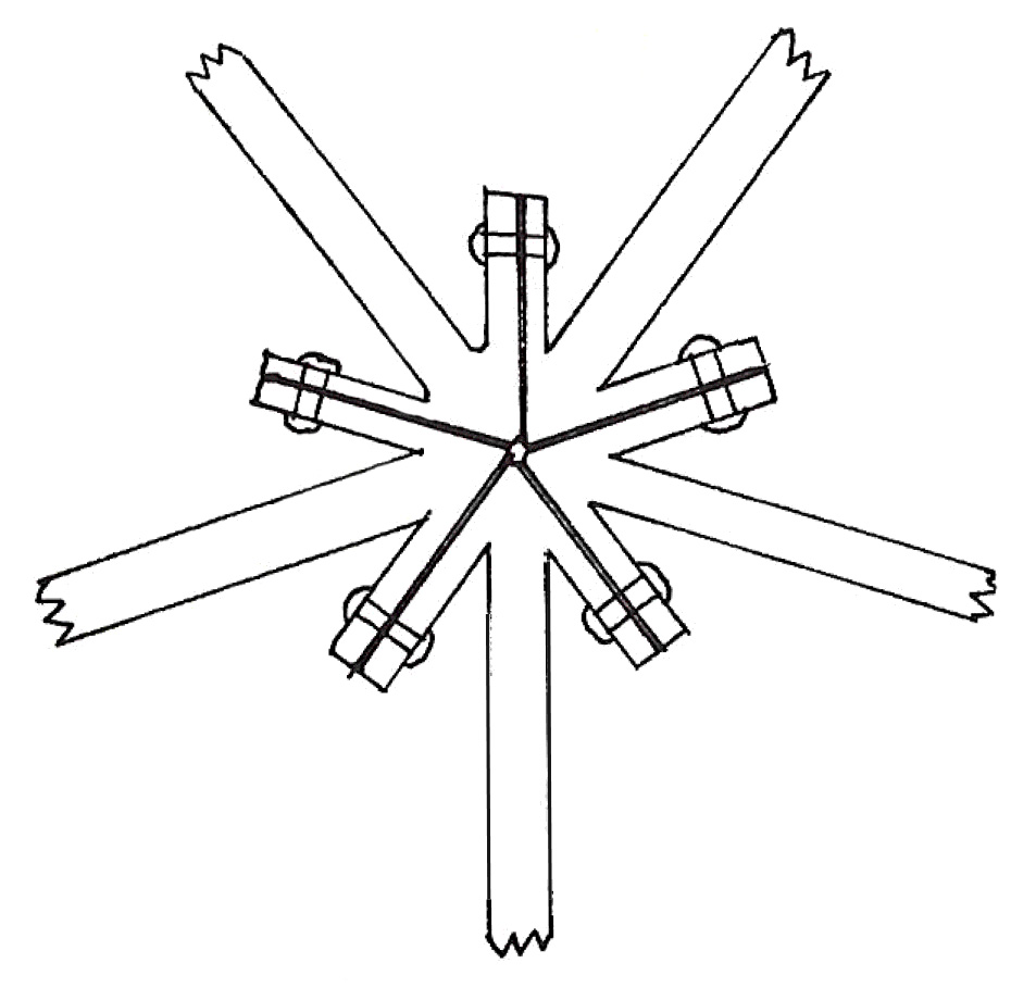
6 When some parts dominate others, there is a hierarchy created and the parts must be differentiated. In our illustration, we show five edges of an icosahedron stacked on top of one another. With the icosahedron, it is possible to have both ends of each edge occupy similar positions, but this is not always true.
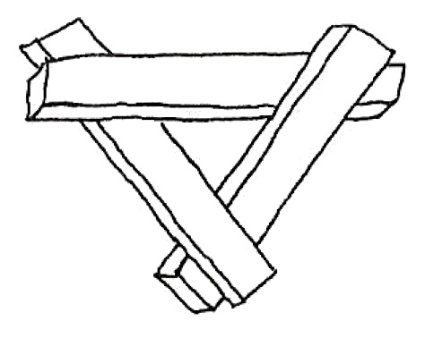
8 The creation of one hierarchy may create the need for more. For instance, if you wish to use a hierarchy of stacked edges to make a simple triangle, then you must also create a hierarchy between ends of the same edge. The two ends of the same edge have different ranks.
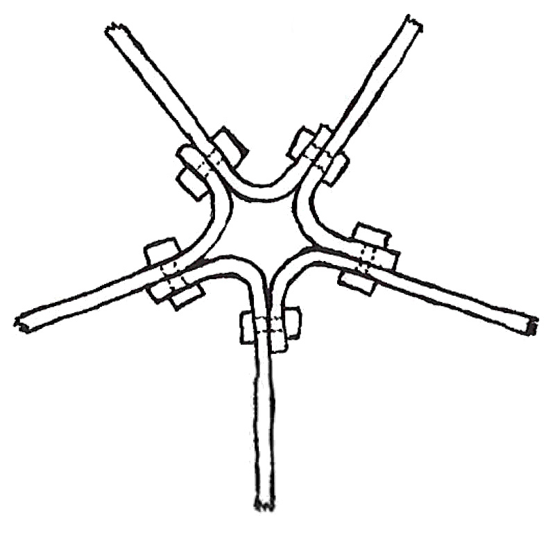
10 Very often we don’t have the structural members actually touching each other. Then we avoid the edges’ problem of sharing, trading or dominating—we push the entire problem on to the joint. The joint must accommodate all the connecting members, and it shouldn’t demand that they have elaborate ends or different kinds of ends. The joint must also be strong and inexpensive.
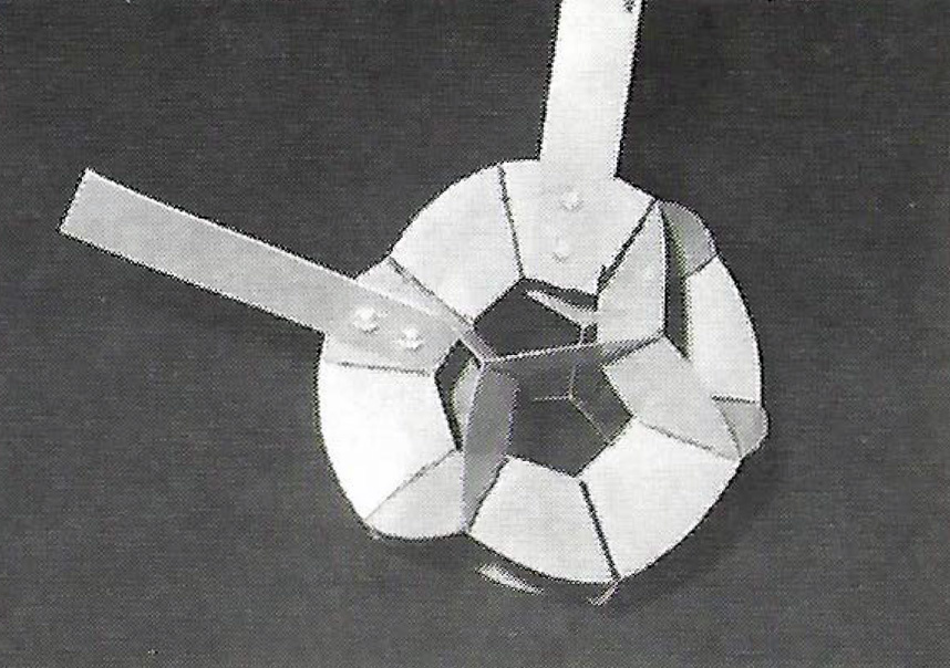
11 If the joint is a ball and the A, B and C connections are simply holes which the members screw into. All holes of the same type are identical, and the ends of all structural members are identical.
12 This is a wonderful feature because you can’t make mistakes—there are no right and wrong holes of a certain type. The joint shown in Figure 15.160 has 12 threaded holes for the A lines in the thirty-one zone system. Joints made this way are expensive, and the connectors at the end of the structural members are expensive. A common inexpensive connecting system is a joint made of multiple interconnecting flanges with the flattened ends of the structural members bolting against the flange of the joint. Joints made of flanges can be simple flat stampings that lock together or are welded together.
13 Flanges bring problems. What if you must connect two joints, and you find that once you bolt one end of your member to one joint it can’t bolt to the other because the flange is turned the wrong way? The specialization of a flat end and a flange has brought problems. The end of the structural member could be made to swivel. That is expensive. The joint could be made so that this problem never arises. Unfortunately, our second solution is not always possible. To make a thirty-one zone joint where each connection is a flat flange and which is impossible to put together incorrectly, you have to devise a pattern that passes through each connecting point only once and is regular (you can’t tell the pattern that surrounds a connection from the pattern that surrounds any other connection of the same type).
15 This is impossible to do in the case of the thirty-one zone star. You can make a flange joint for the thirty C connections. The C lines can have the specialization of flange orientation while still avoiding the clumsiness of having to arrange themselves in a hierarchy. The flanges are the edges of an icosahedron or a dodecahedron.
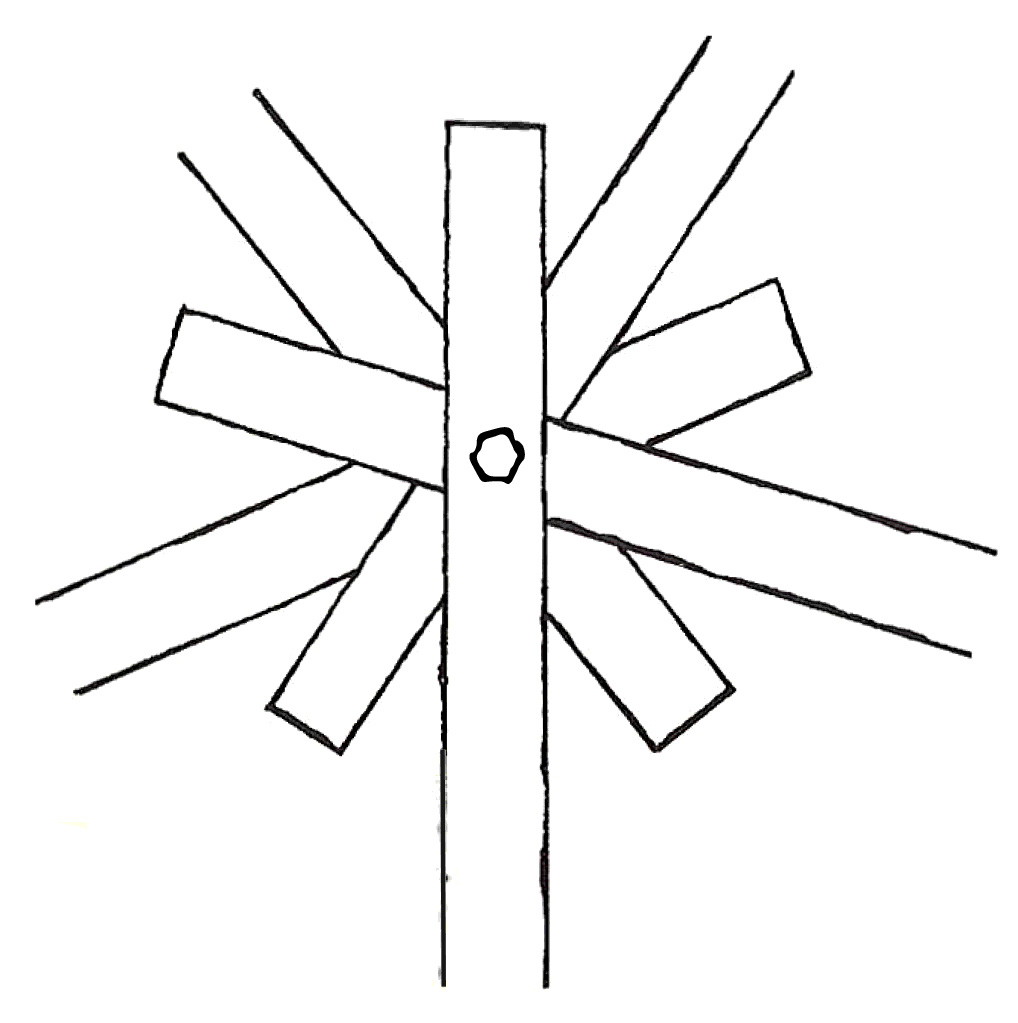
16 Three interlocking rectangles at right angles to each other form a flange joint for the 12 A lines, 6 C lines and 12 B lines.
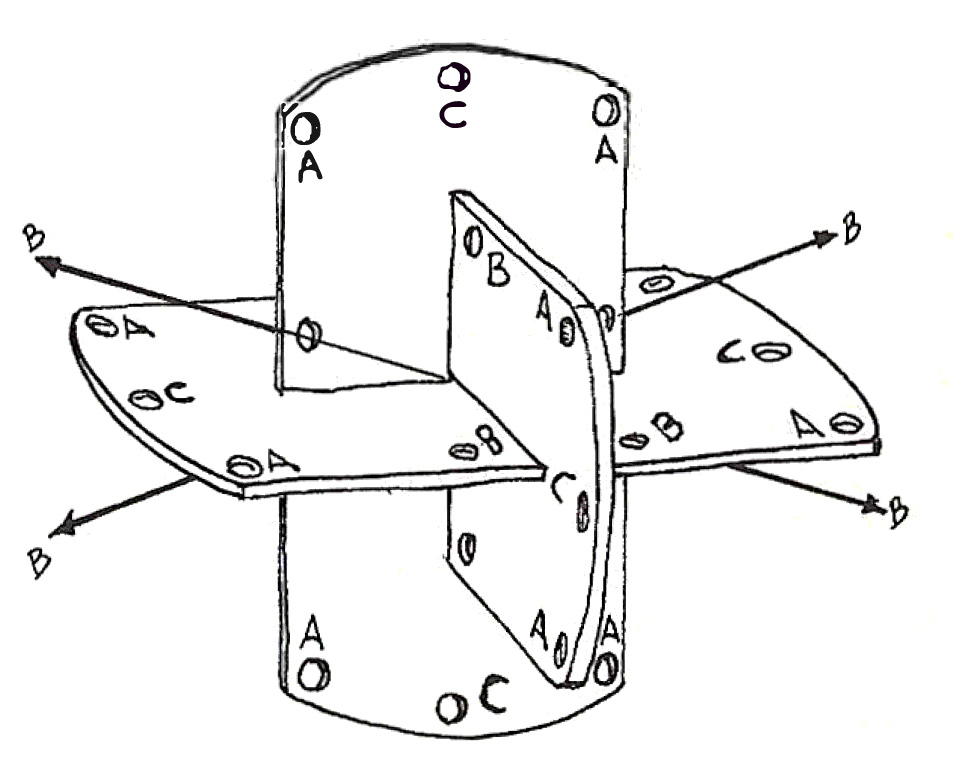
18 Note! These are three perpendicular R sections.
19 There is a mistake proof flange joint for both A and C connections if one hierarchy is introduced. You must always orient the joint to suit the A lines.
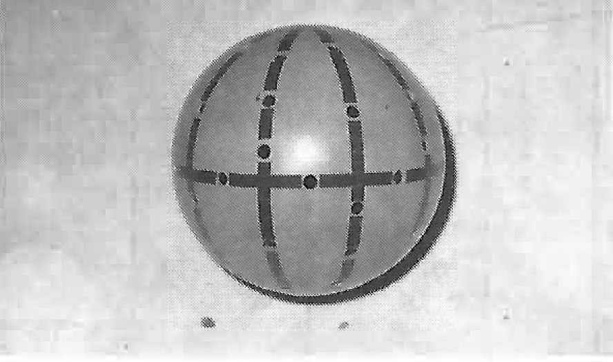
20 This joint is shown in the photo of the wooden model of the three intersecting planes.
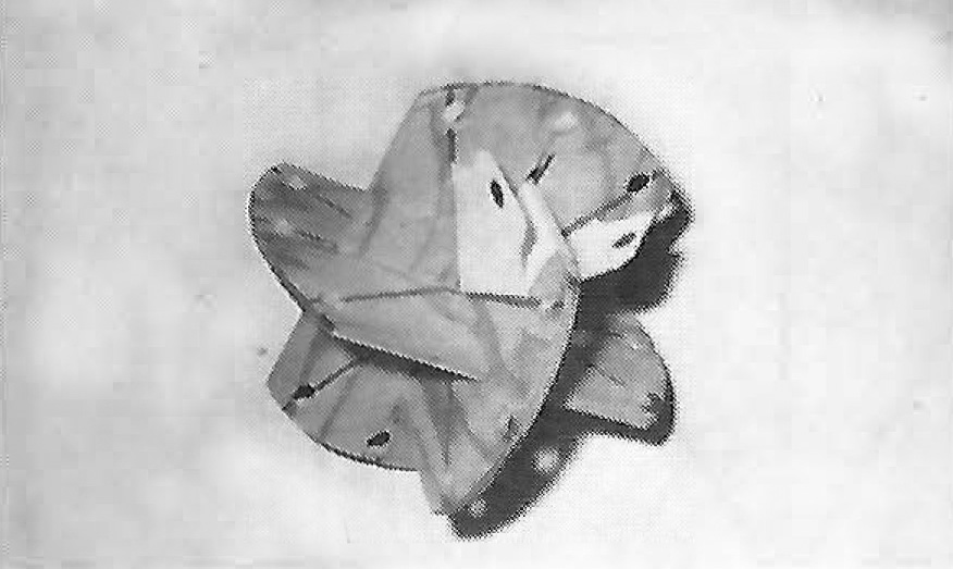
22 Two of the flanges for the missing C lines are added. This joint is completely regular until the addition of these C flanges—they are not in the same plane as their neighboring A flanges. We thus have two types and lose our regularity.
23 A good flange joint for the thirty-one zone star is made of six interlocking disks—five R sections and one T section.
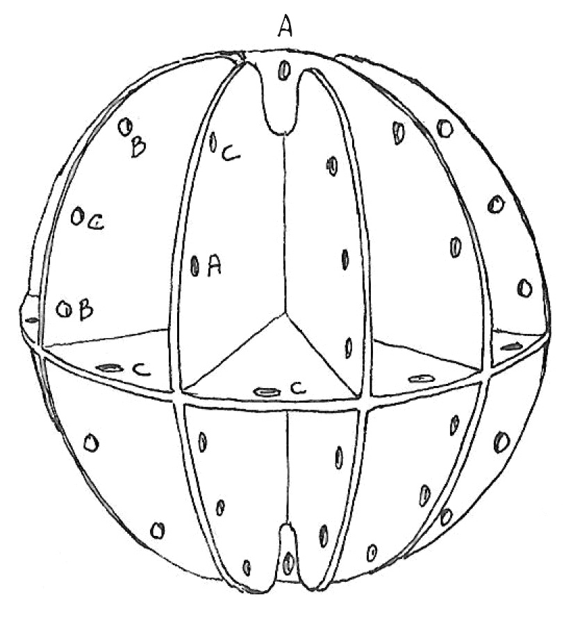
26 This creates an irregular icosahedron which passes through each of the sixty-two connecting points and decides automatically the orientation of sixty of the flanges. The pole points of this figure are A connections and one of the five intersecting R sections must dominate the others to determine the flange orientation. This joint can have part or all of the R sections in place depending on which connections are needed.
14.1 Octet Truss
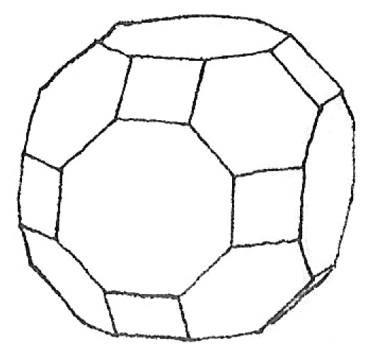
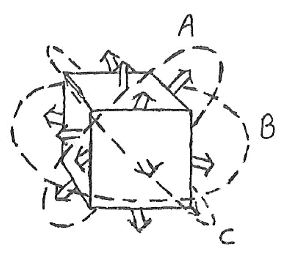
27The widely used octet truss is based on the star that passes through the midpoints of the edges of a cube. (Or, equivalently, the midpoints of the edges of an octahedron, the midpoints of the faces of a rhombic dodecahedron, the vertices of a cuboctahedron.)
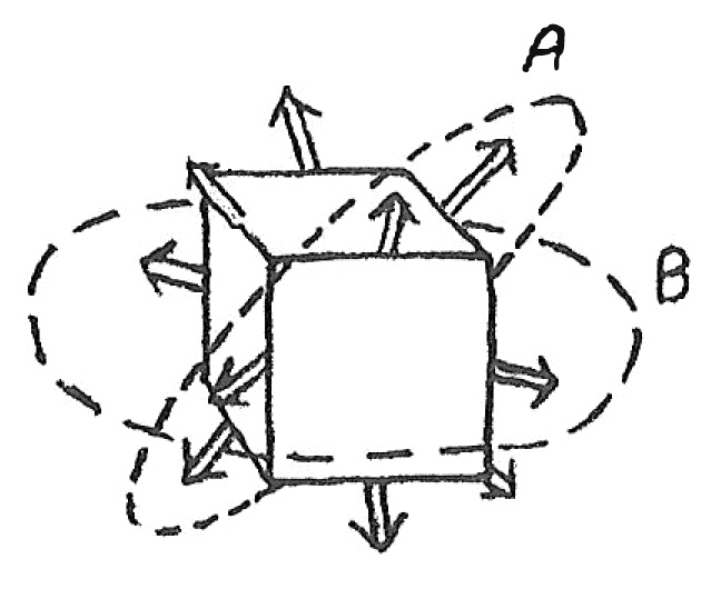
29 This is a singular star with four sections (A sections in drawing) containing three lines at 60° to each other and three sections with two lines at right angles (B sections). The zonohedron whose edges are parallel to the lines of the star is the truncated octahedron.
14.2 The Mero Space Grid System
31This system is based on the octet truss star plus three more zones which pass through the face midpoints of the cube which has the other lines passing through its edge midpoints. This singular star has three sections (B sections) with four lines intersecting at 45° to each other, four sections (A sections) with three lines at 60° to each other and six sections (C sections) with two lines at 90° to each other.
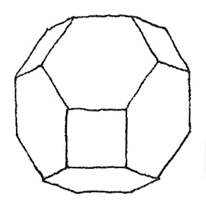
33 The zonohedron associated with this star is the truncated cuboctahedron.